GDBC: GilDev Breadboard Computer
An 8-bit computer entirely made out of TTL logic chips on a dozen breadboards.
Distinctions
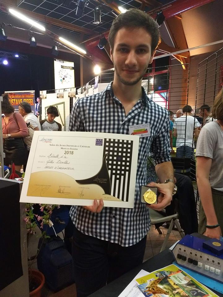
- First prize in “Senior Solo” category at the 2018 Monts’ Young Inventors and Creators Show: 300 € given by the UTAI, 300 € given by STMicroelectronics and a gold medal of the Concours Lépine. Showcased alongside The Simple 4-Bit Computer and the Kenbak-1 Replica projects
Informations
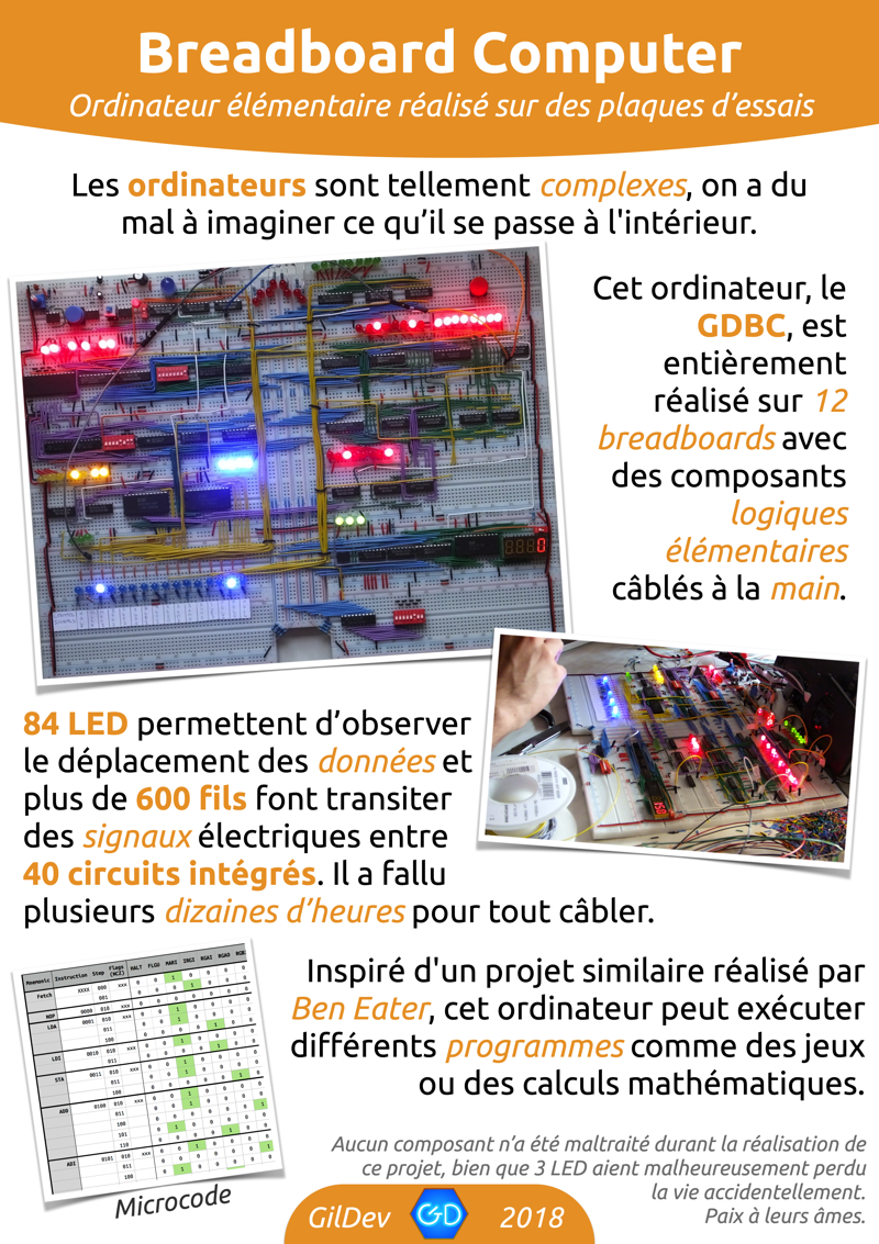
- Inspired by Ben Eater’s Breadboard Computer
- Presentation poster for Monts’ Show (in French)
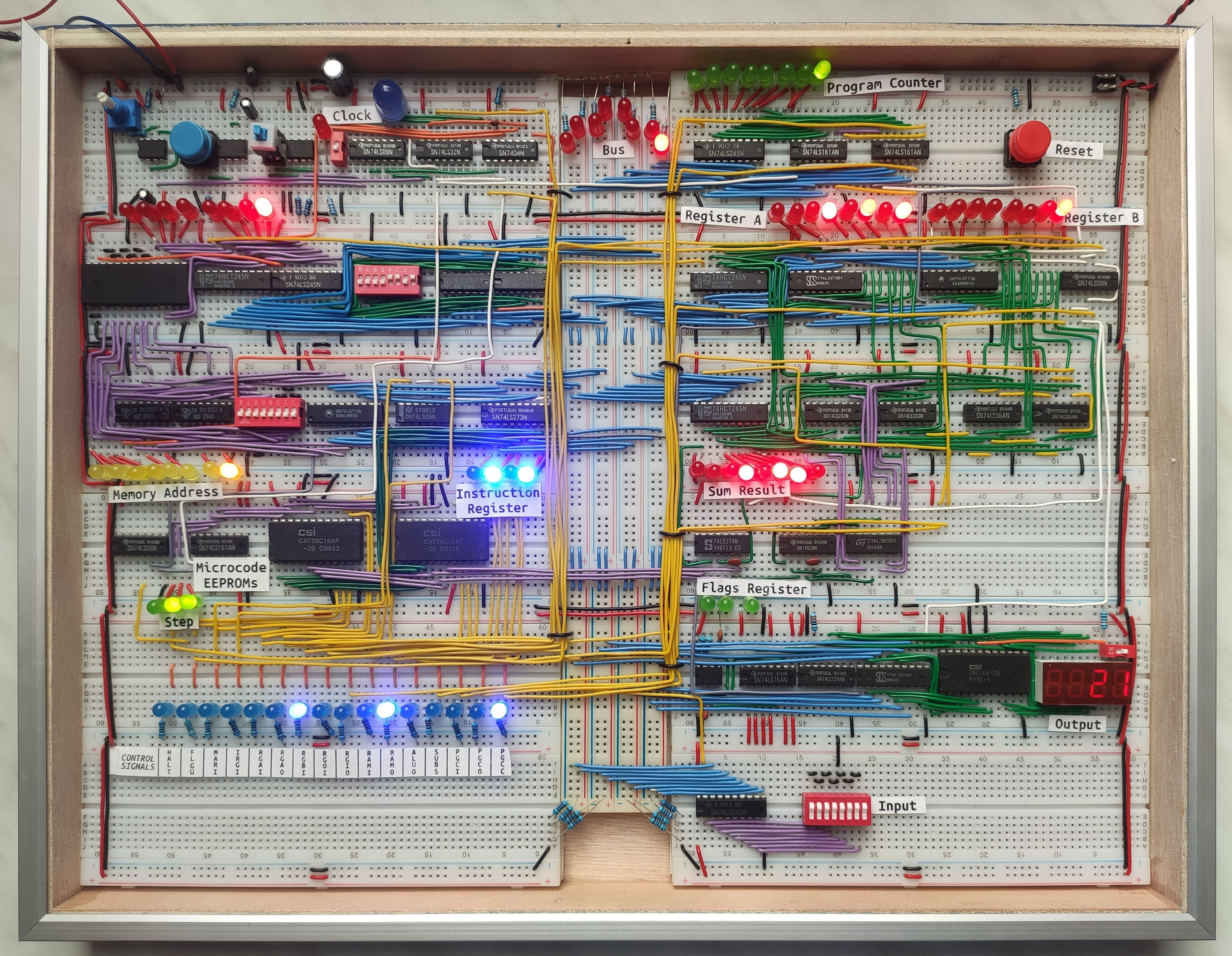
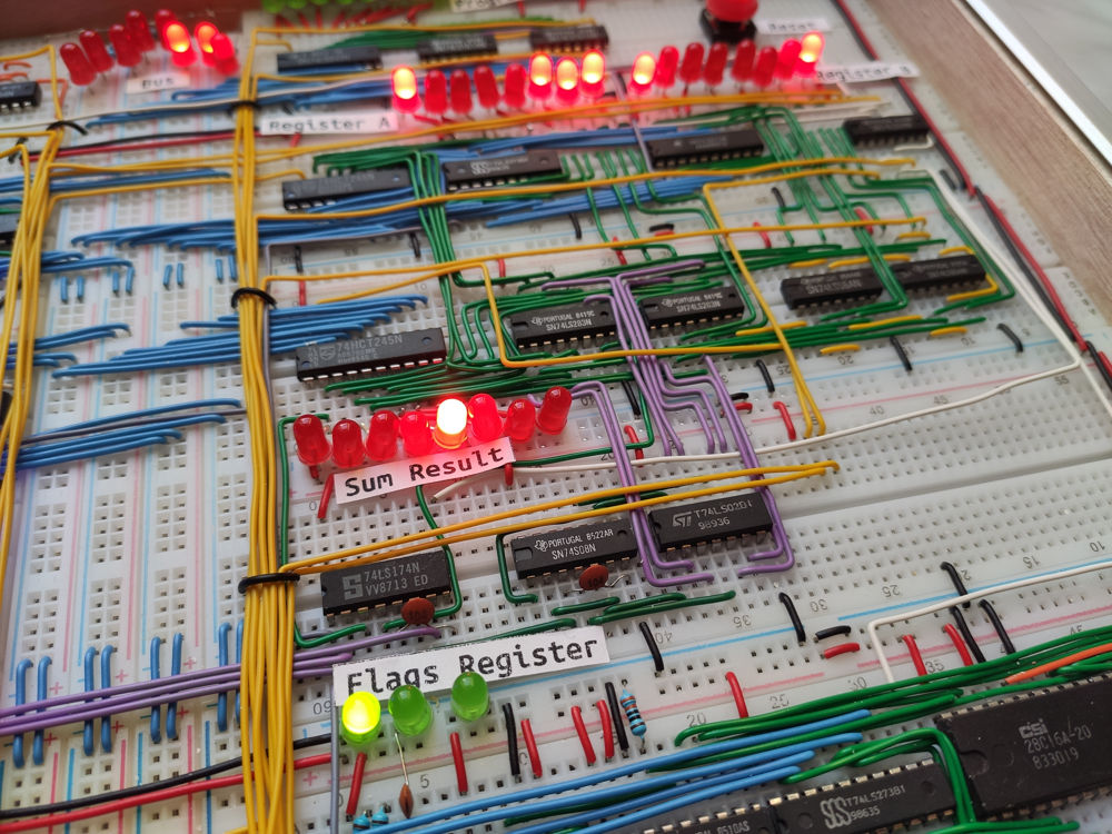
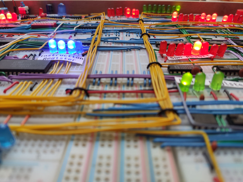
- 84 LEDs
- 40 integrated circuits (mostly 74LS logic chips)
- more than 600 hand-bent wires
Documents
Details
If you didn’t know, I love low-level computing: that awesome fusion between electronics and computing. So what better than to create my own computer and lay it out on breadboards to make it look really cool?
The initial idea came from Ben Eater’s wonderful video series on building an 8-bit breadboard computer.
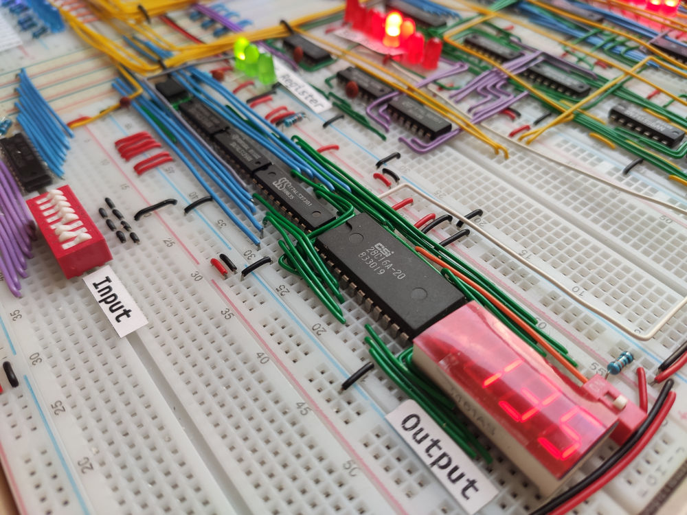
Most of my modules are in big part inspired by Ben Eater’s ones, although they all have slight modifications: for example I have created a simple input module. I’m also using 8-bit memory addressing instead of Ben Eater’s 4-bit addressing, that means the GDBC has 256 bytes of memory instead of 16, which makes the computer a lot more usable! Oh and the instruction set is also quite different.
The integrated circuits are mostly TTL logic chips from the 74LS series (LS instead of HC because my school had many of them unused in stock, and it’s more vintage 😃).
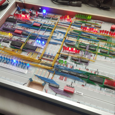
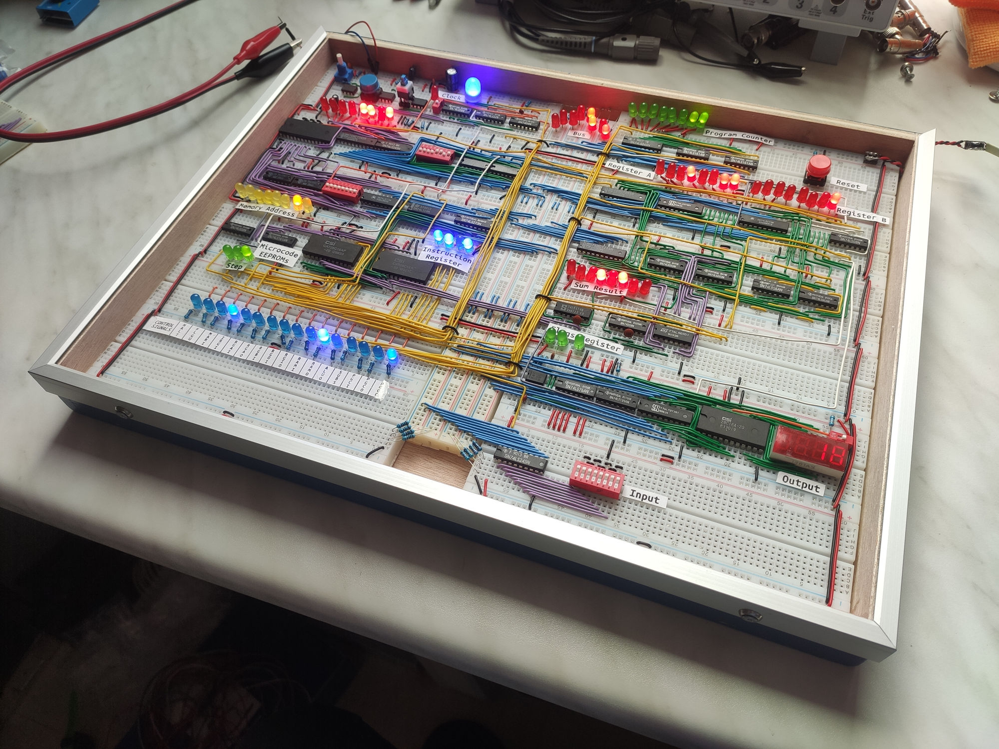
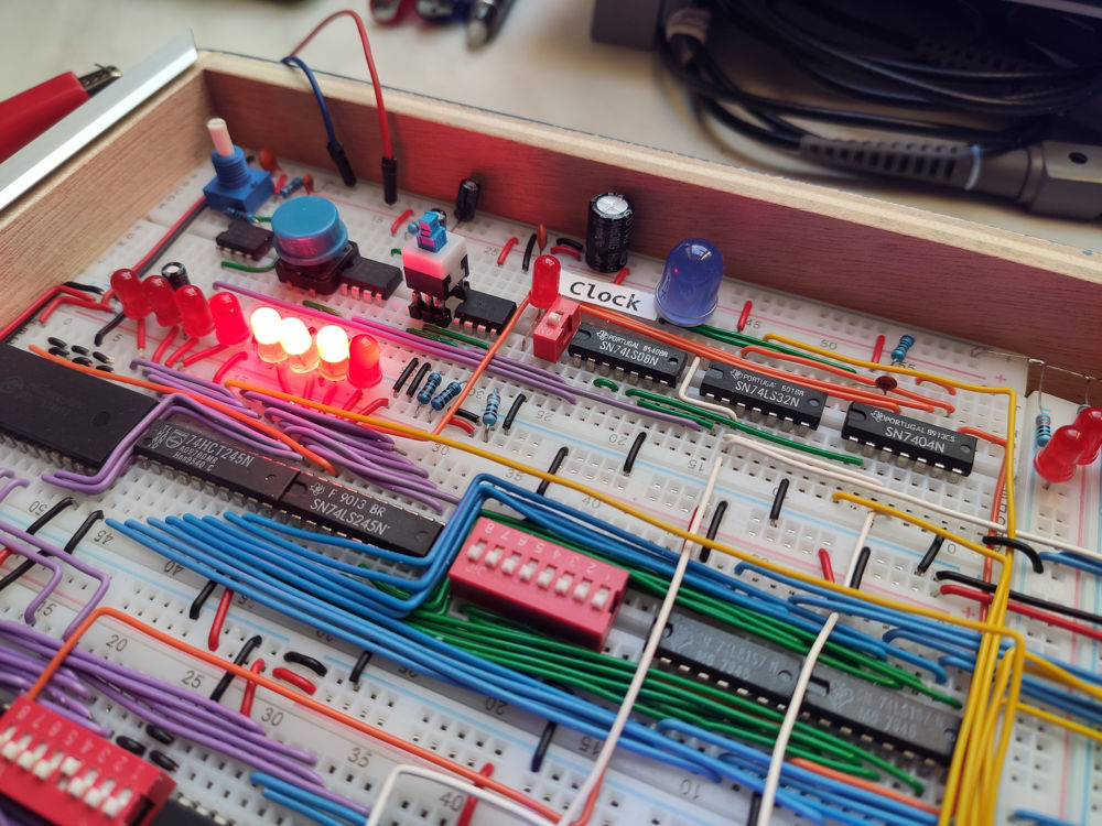
Each wire is hand-bent and has a specific color depending on its purpose (white is clock, yellow for control signals, blue is bus, green and purple are intermediate connections, grey is reset, orange is programming mode…).
There are 12 breadboards, defining the different modules you can find in the architecture.
The clock’s frequency can be adjusted using a potentiometer, from about 0.5 Hz to about 400 Hz (could probably go higher but I haven’t tried, it’s a lot more fun to look at the lights blink 🤩).
The computer is mostly stable now, it may sometimes be hard to write a value in memory in programming mode, because I’m not using a dedicated button for this but the clock step button that sometimes requires multiple press before the input value is registered.
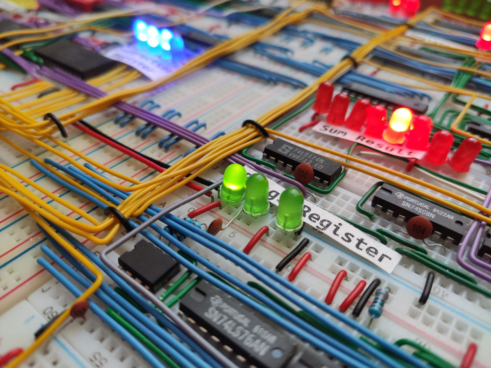
I also had bouncing issues when updating the ALU’s flags and had to add a few capacitors to smooth out the ripples.
The next version should have a resistor for each LED or for LED power lines, because right now the ICs are driving the LEDs without limit and it may affect those LEDs’ brightness and/or disturb RAM write operations when many are lit.
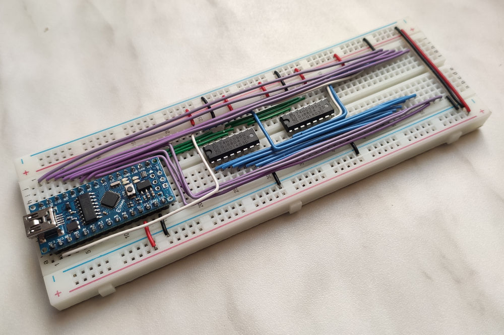
The bottom left breadboard is also empty and it would be cool to have an Arduino Nano placed here to load a program in RAM at startup and/or on demand.
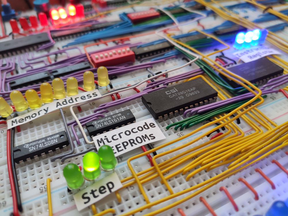
There’s one separate breadboard, which is the EEPROM programmer, the same as Ben Eater’s one.
To protect the GDBC from dust and adventurous hands, my father and I built a painted wooden frame with a cut Plexiglass cover. A little hole on the back gives access to a connector that allows powering the computer over 5 V.
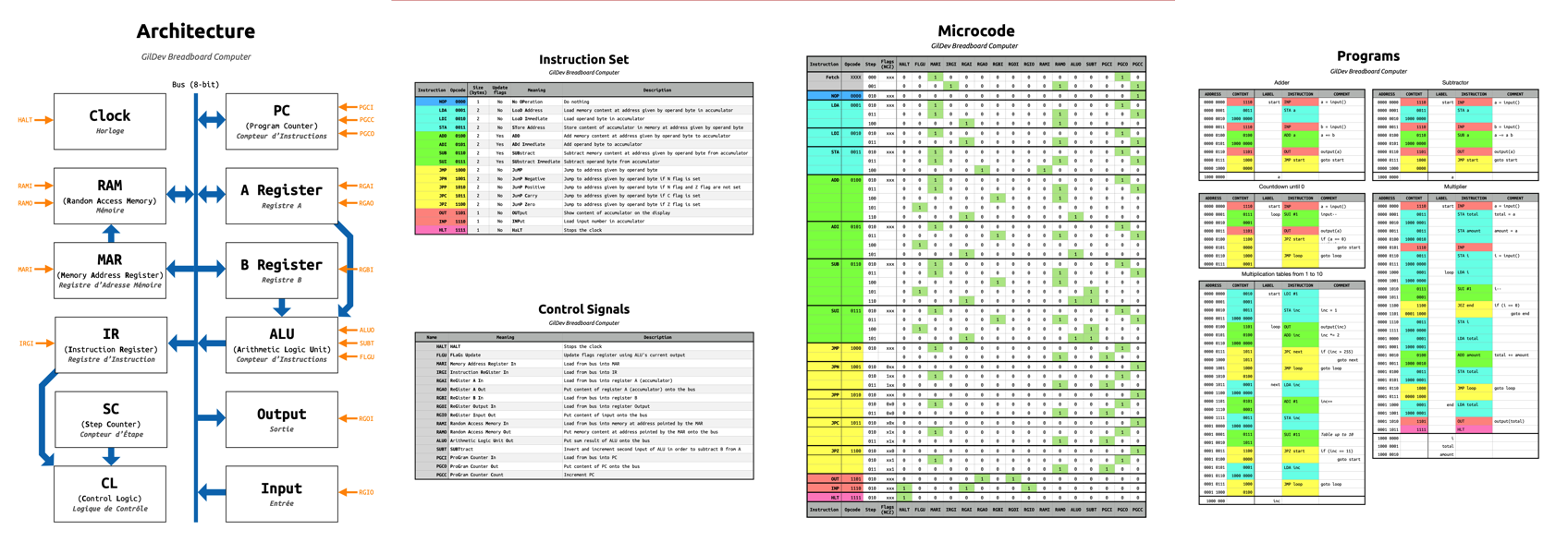
You can find the documentation files at the top of this page: Architecture, Instruction Set & Control Signals, Microcode and Sample Programs.
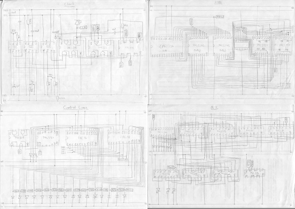
All the electronic schematics are hand-drawn and I haven’t got the time to draw them again on the computer…
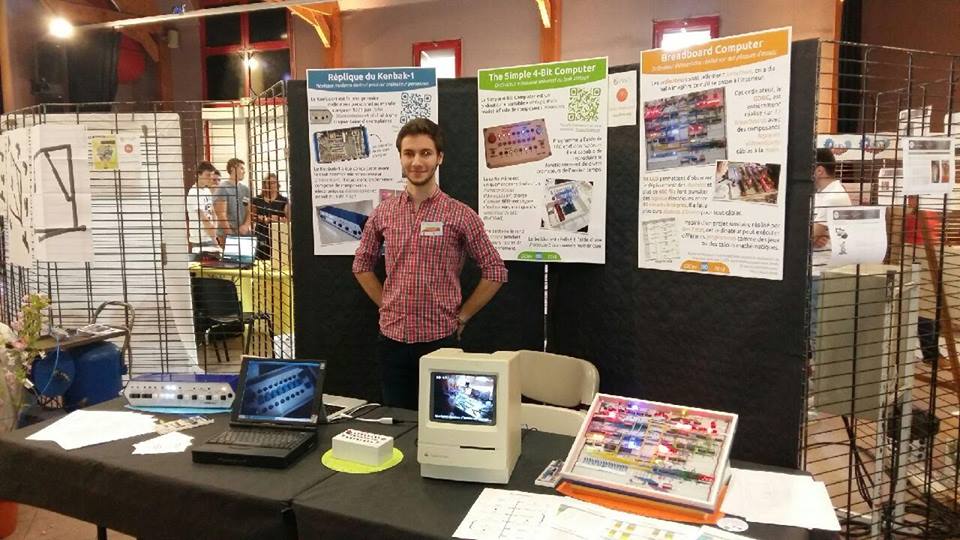
This computer was showcased at the 2018 edition of the Monts’ Young Inventors and Creators Show, this is the second time I participated, the first time was in 2016 with the IntelliCasier.
I won first prize with my three showcased projects about vintage computing, the two others being The Simple 4-Bit Computer and the Kenbak-1 Replica.