GDBCs: GilDev Beautiful Clocks
Three beautiful electronic clocks, each displaying time differently. They are made out of RGB LEDs and copper wires as the structure, with 3D-printed and painted cases.
Distinctions
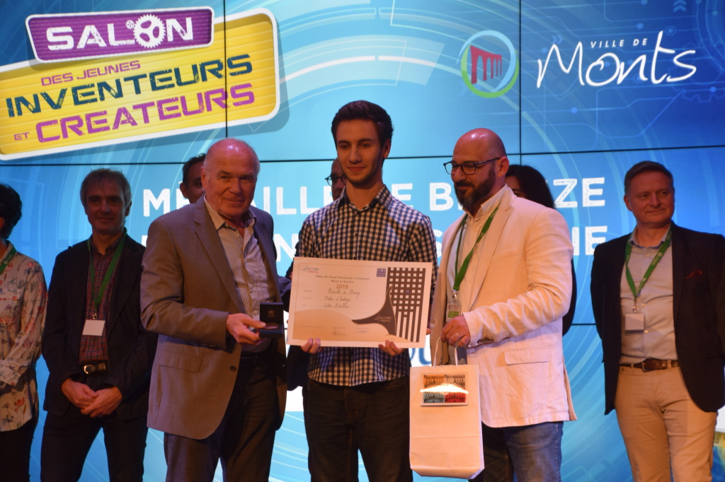
- Third prize in “Senior Solo” category at the 2019 Monts’ Young Inventors and Creators Show, bronze medal of the Concours Lépine
Appearances
- Interview in the TILT television show hosted on TV Tours (video down below) on May 17, 2019
- Article sur on ISTP’s website (École des Mines de Saint-Étienne, my engineer school)
Informations
- Inspired by mattaw’s “Driftwood Binary Clock”
- Atmel AVR (ATtiny85) microcontroller programmed in AVR C
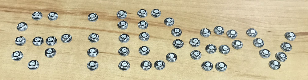
- LED RGB WS2812B with embedded controller
- 3D printed cases and wire-bending tools
- Softwares used:
- Programming: AVR C on Sublime Text 3 with PlatformIO
- 3D modeling: Fusion 360
- Electronic CAD: DIYLC
- Poster & explanation sheets drawing: Apple Pages

Details
I saw an article on Hackaday showcasing a funny BCD clock using RGB LEDs made by mattaw. It uses a structure made of bent copper wires, used to hold the LEDs along with powering and controlling them.
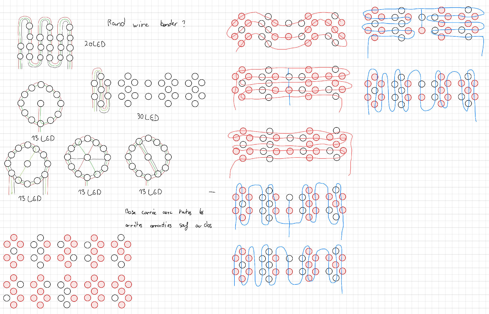
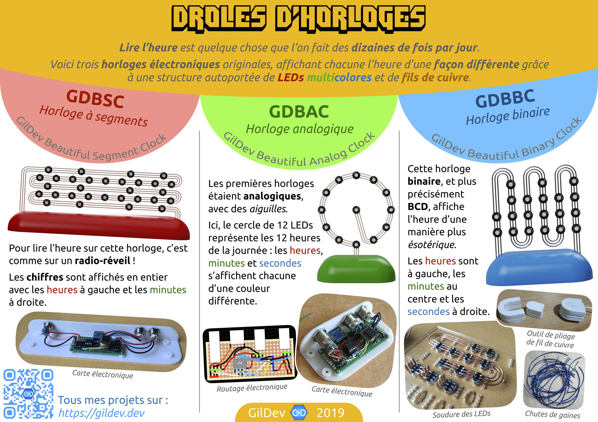
I immediately wanted to make my own variant with wires bent differently, so that it would have three continuous wires. This one is called the GDBBC (GilDev Beautiful Binary Clock (yeah you can imagine another meaning at first…)). I started drawing different imagined structures along with the features I wanted.
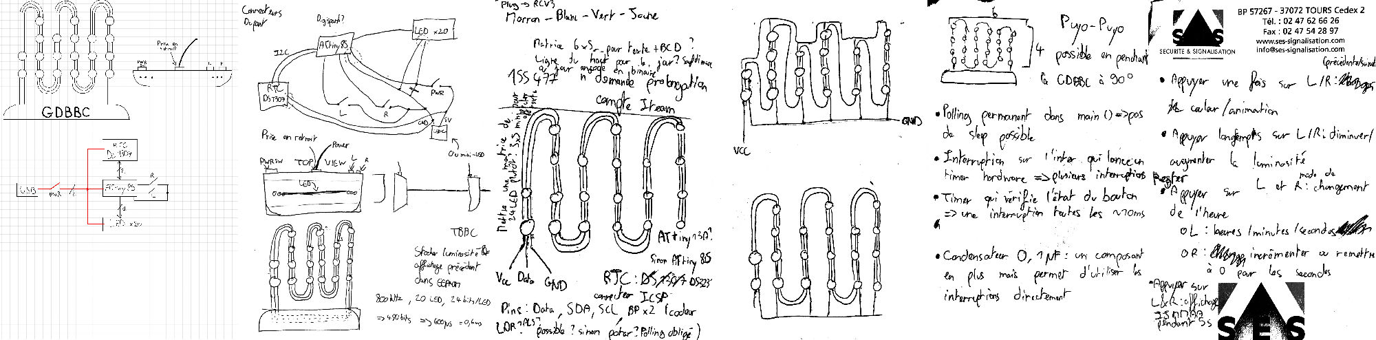
The idea seemed interesting enough to be showcased at the 2019 edition of the Salon des Jeunes Inventeurs et Créateurs de Monts (Young Inventers and Creators Show, which is like a small Maker Faire for invententions), so I decided to make two more clocks in order to enhance my collection. Each clock shows the time a different way, hence the GDBSC (GilDev Beautiful Segment Clock) and the GDBAC (GilDev Beautiful Analog Clock) were born. The three clocks altogether are named GDBCs for the plural. 🙂
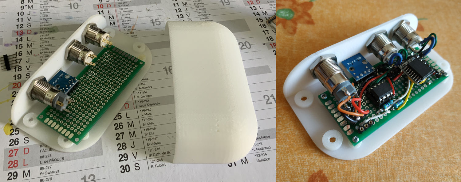
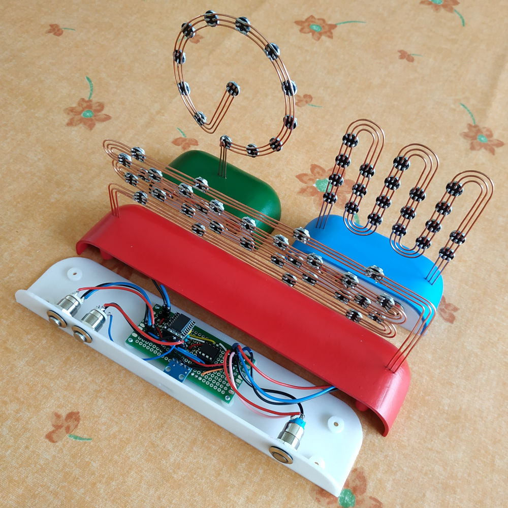
As shown in the drafts, the electronic board which controls the LEDs chains includes a DS3231 real-time clock, two buttons for settings and an ATtiny85 to control everything. The whole is powered via a micro-USB port.
I modeled my imagined clocks on Fusion 360 in order to make the soldering guiding sheets and the 3D-printed cases.
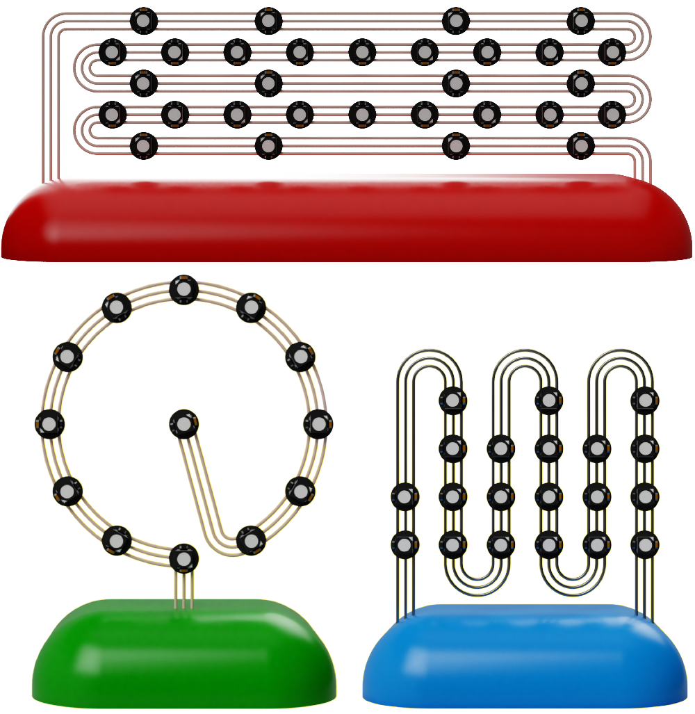
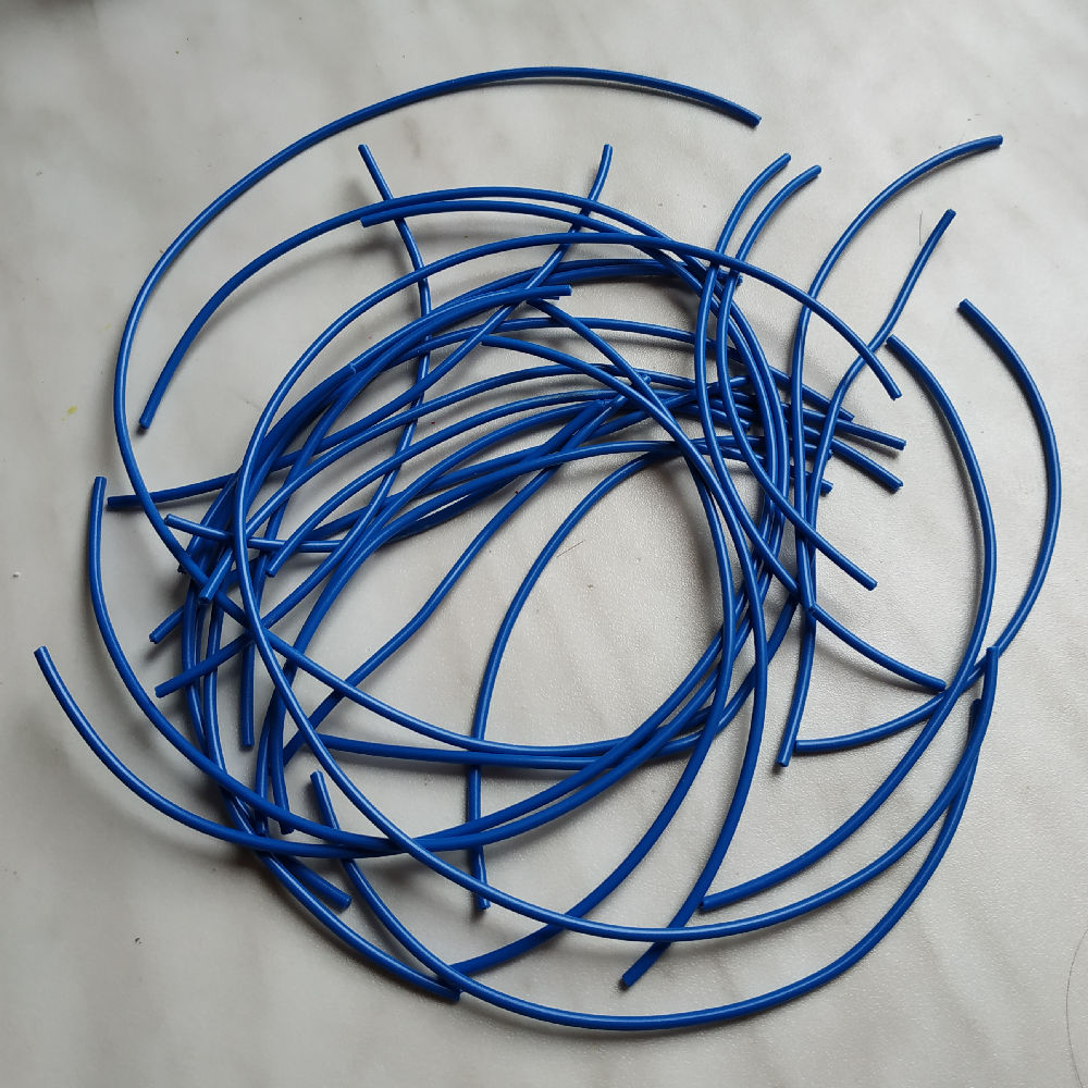
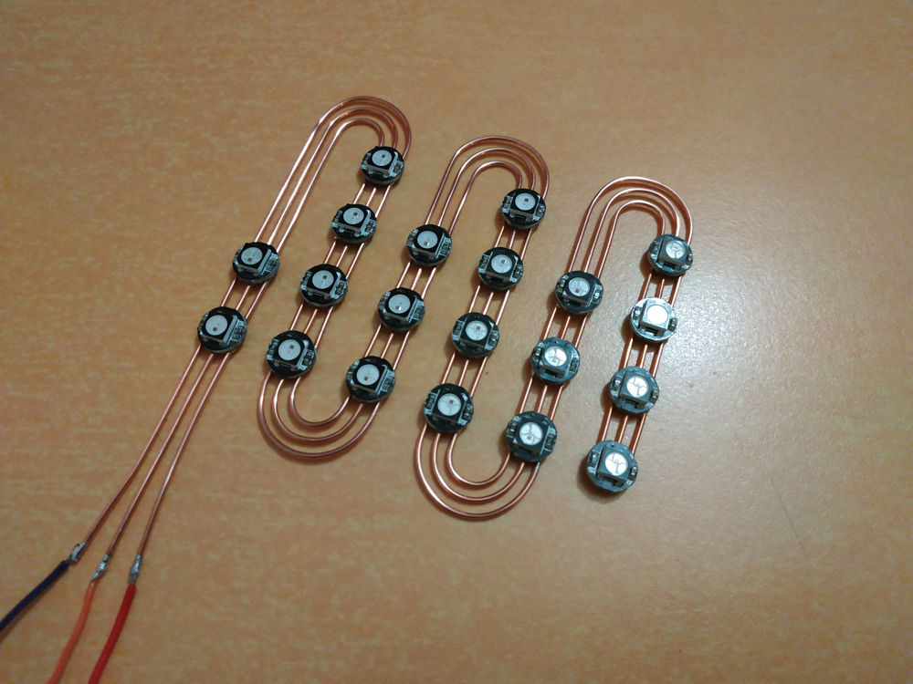
Structures are made using three copper wires: power, data and ground. They come from standard 1 mm (18 AWG) electrical wires from which the sheat has been removed.
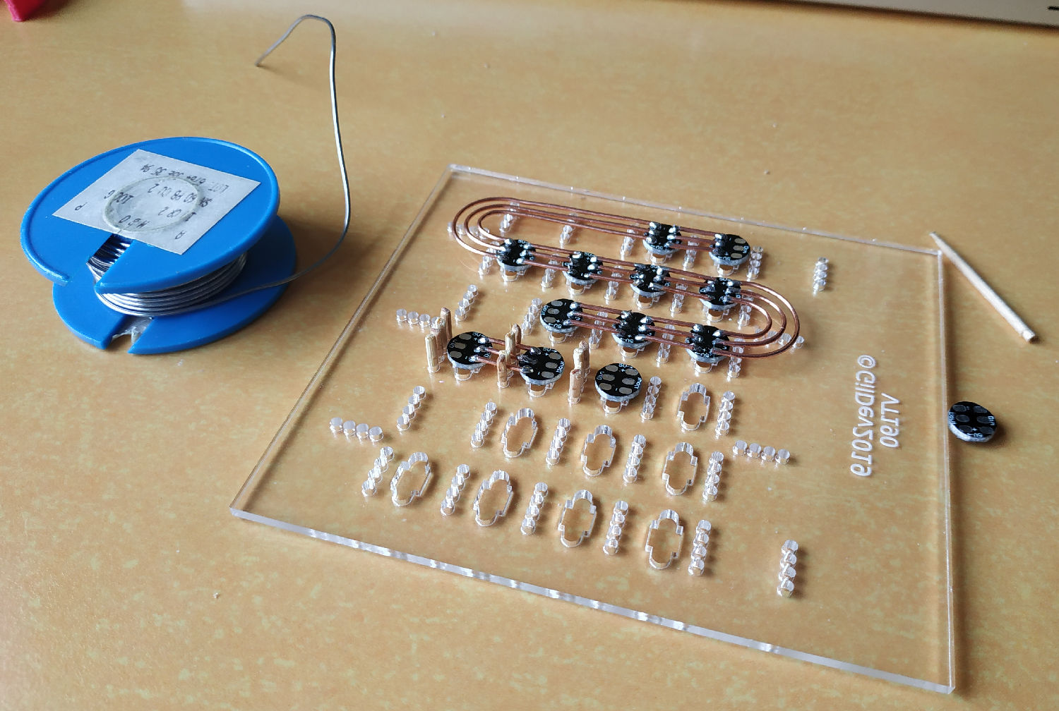
The guiding sheets are laser-cut clear acrylic, guiding each LED and copper wire using toothpicks to hold them in place. The toothpicks are inserted in little holes on each side of the wires. The GDBSC having such large horizontal wires, it has two small laser-cut plexiglass parts clipped together on each side in order to hold all the wires vertically.
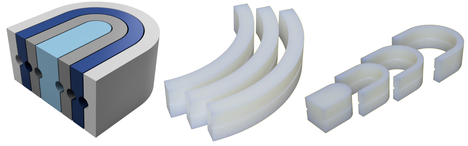
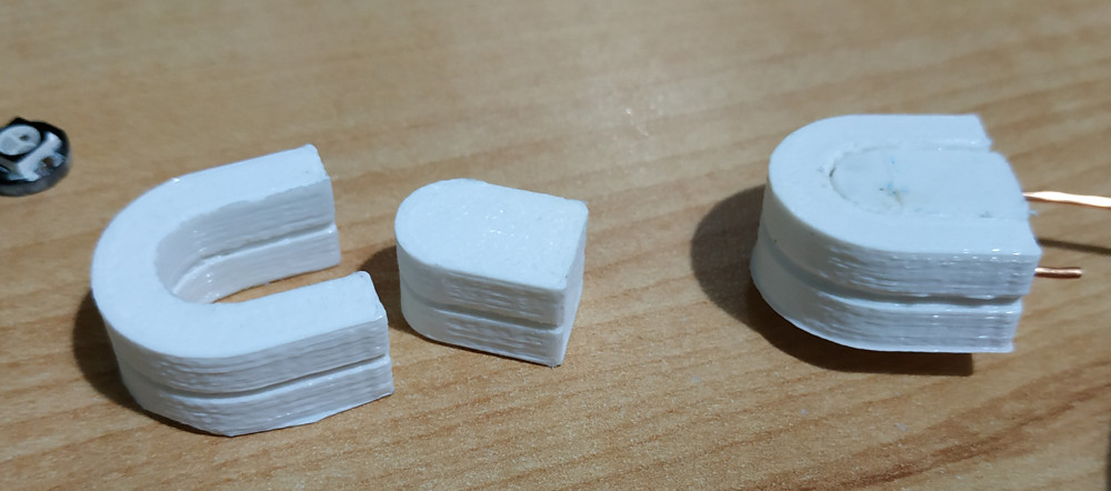
I’ve also modeled and 3D printed little “wire-bending” tools for each clock in order to get the best possible curves.
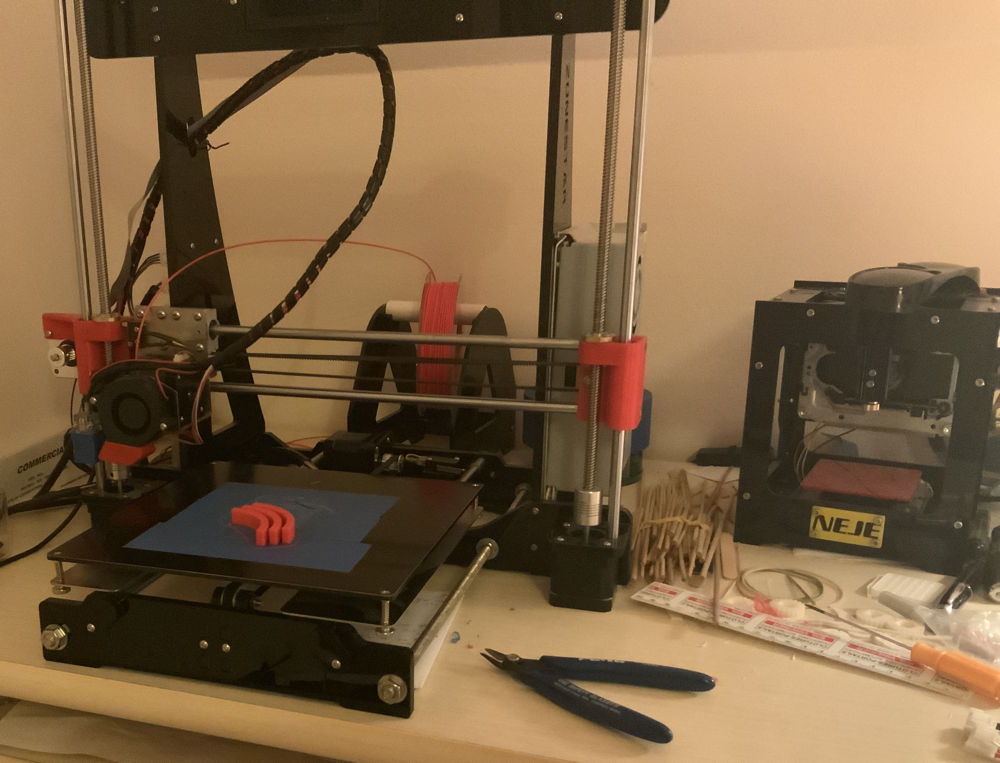
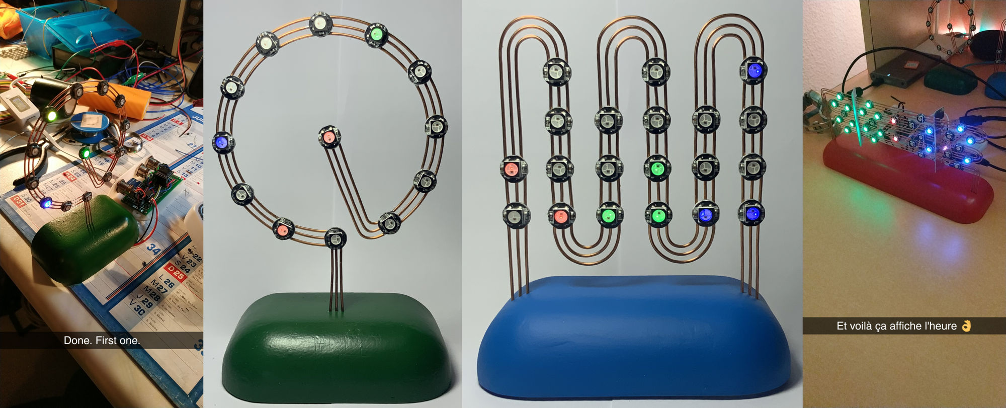
After a few hours of soldering for each clock, the structures were ready:
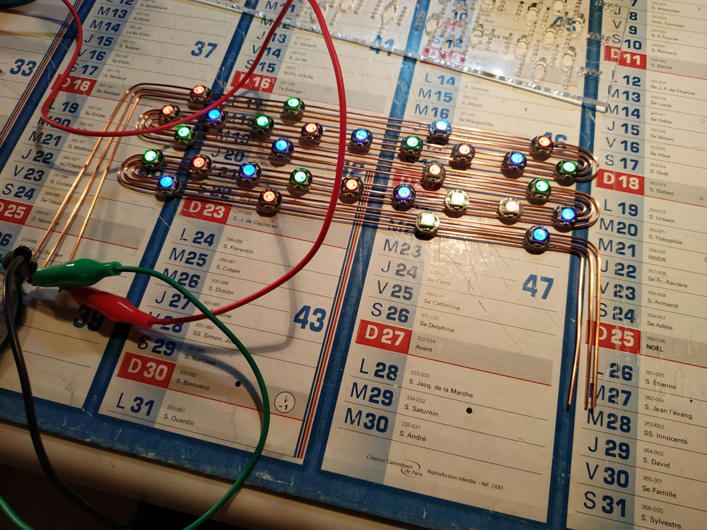
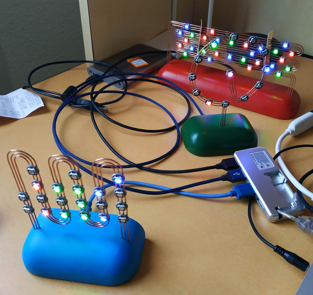
Now is the time to test it using the circuit made on breadboard:
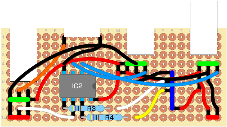
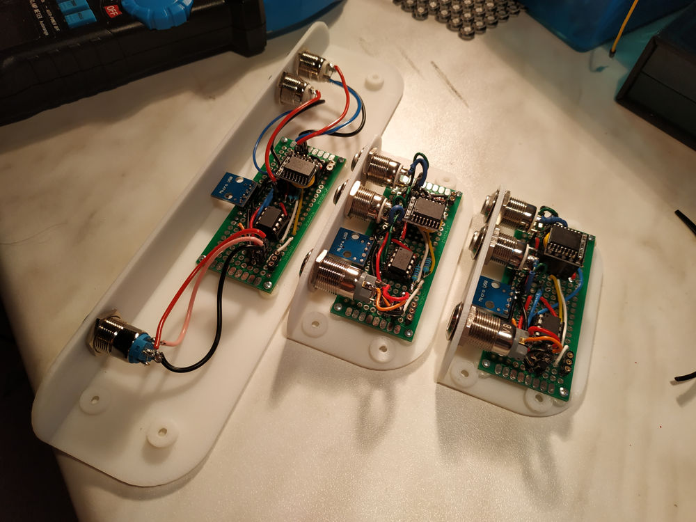
The electronic board was made on “prototyping boards” that I had in stock. I’ve organized components using the DIYLC software. A few modifications were made live, because wires don’t enter the case from the same place (GDBBC: each side, GDBAC: middle) and they could collide with some components on the board as the space inside the case is quite limited.
Cases shown above were made at the same time. They were not printed on my personal printers (I only had the Zonestar P802N at that time and it needed some tuning) but on a Stratasys printer in ABS.
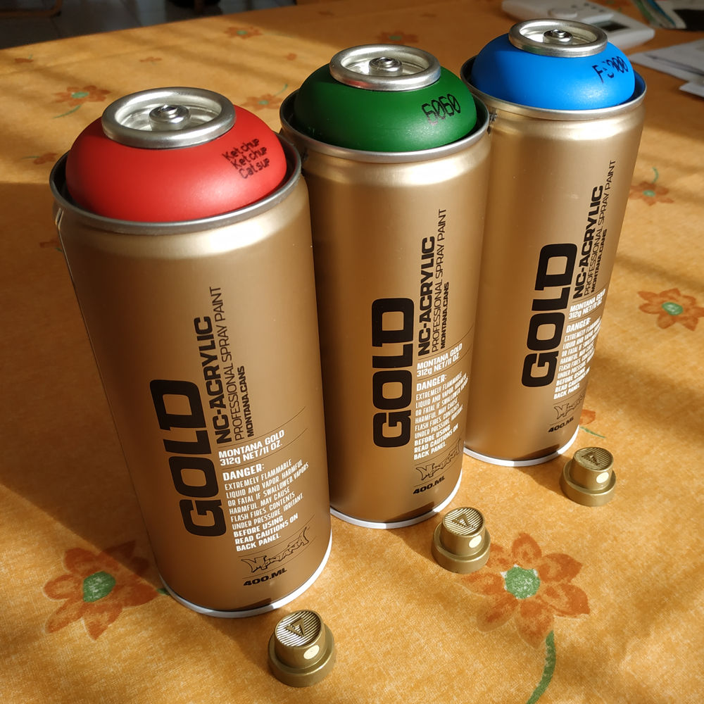
The cases were missing a few colors, so I wanted to make each clock with its own color. I made a few acrylic paint tests after two mastic layers (so it would hide the layers, as the layer height isn’t customizable on the Stratasys).
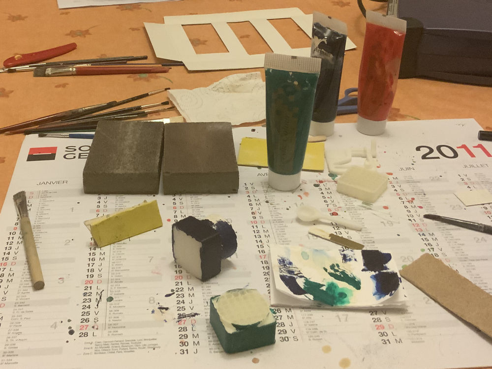
In the end, acrylic spray paint gave the best results because it doesn’t leave any brush marks.
I then continued the programming on a single code base with a compilation option to choose the clock type.
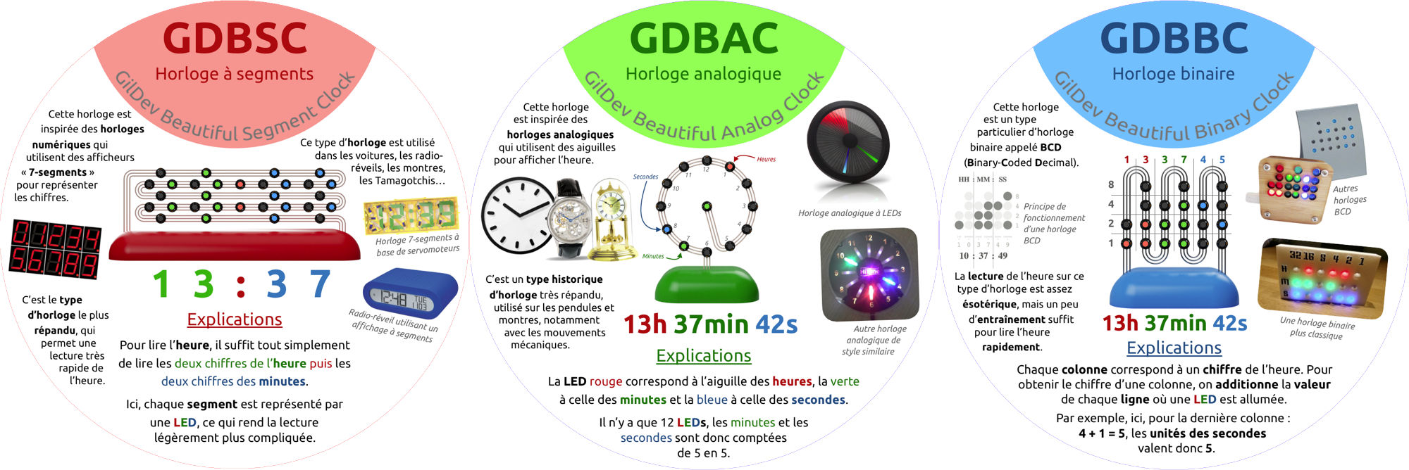
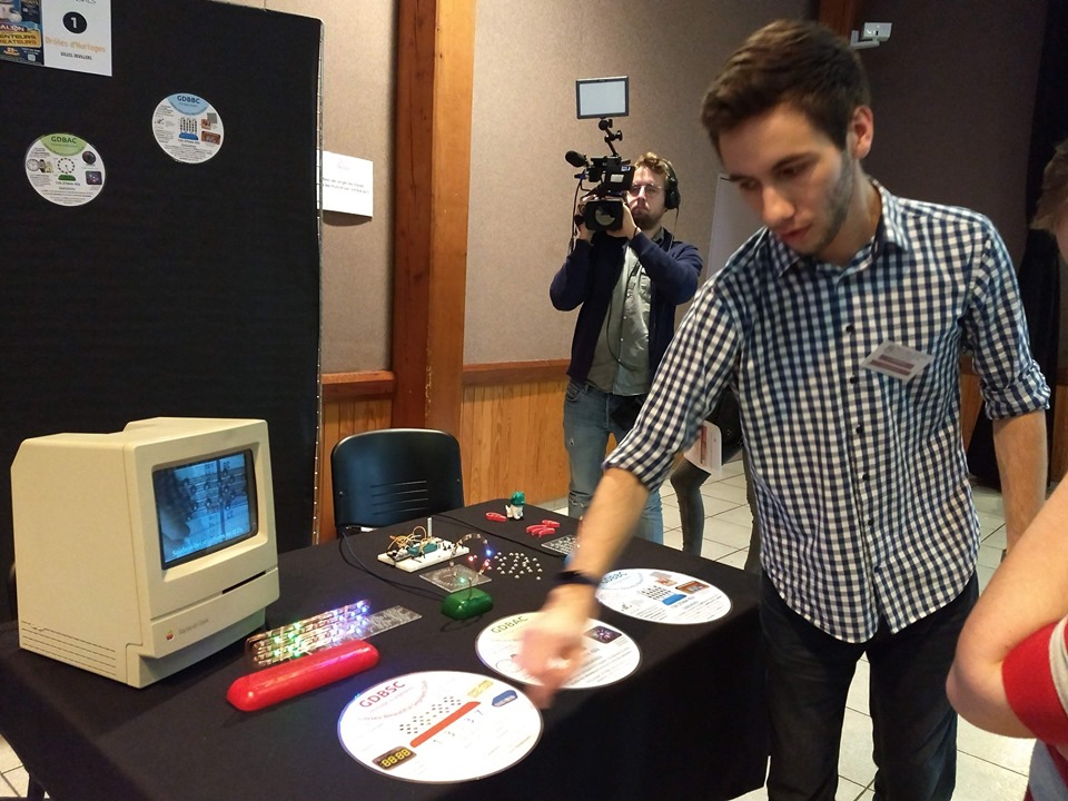
I then showcased my three clocks at the 2019 Monts’ Young Inventors and Creators Show in front of a very interested audience. I made a poster for the event along an explanation sheet for each clock:
Finally, here are a few photos of the show. You can see the modified Macintosh, which was also placed on my booth at the 2018 edition of the show. It was playing the making of video you can see at the top of the page.
A few persons asked me to make more clocks of that style (mainly the GDBAC) so they could buy one. I’m thus looking at making a PCB and really finish the firmware (add date display and DST).
